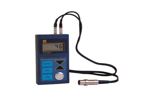
Guidance: Ultrasonic Thickness Gauge Indications Excessive or Undersized Cause Analysis In the actual inspection work, often encountered with thickness gauge indication value compared with the design value (or expected value), obviously large or small, the reasons are as follows Ultrasonic Thickness Gauge Indications Excessively Large or Small Inferior Cause Analysis In the actual inspection work, it is often encountered that the thickness gauge indication is significantly larger or smaller than the designed value (or expected value). The reasons are as follows: the winch include hand winch, Electric Winch, air winch and hydraulic winch winch Inject Printer,Color Laser Printer,Cheap Laser Printer,High Speed Inject Printer HARBIN QIAN FAN XI FENG MACHINERY CO.LTD , https://www.waterjetwamit.com
1, laminated materials, composite (heterogeneous) materials. It is not possible to measure uncoupled laminates because ultrasonic waves cannot penetrate the uncoupled space and cannot propagate uniformly in composite (heterogeneous) materials. For devices made of multi-layered materials (such as urea high-pressure equipment), special attention should be paid to the thickness measurement, and the value indicated by the thickness gage only indicates the thickness of the material in contact with the probe.
2. The speed of sound is wrong. Before measuring the workpiece, preset its sound speed according to the type of material or reversely measure the speed of sound according to the standard block. When a material is used to calibrate the instrument (usually the test block is steel) and another material is measured, it will produce erroneous results.
3, the impact of temperature. The sound velocity in general solid materials decreases as their temperature increases, and experimental data shows that the sound speed drops by 1% for each 100°C increase in hot material. This is often the case with equipment that is in service at high temperatures.
4, the impact of the coupling agent. Coupling agent is used to eliminate the air between the probe and the measured object, so that the ultrasonic energy can effectively penetrate the workpiece to achieve the purpose of detection. If you select a category or use it incorrectly, it will cause an error or a coupling mark to flicker and cannot be measured. In actual use, due to the excessive use of coupling agent, when the probe leaves the workpiece, the instrument display value is the thickness of the coupling agent layer.
5. There are deposits in the measured object (such as the pipeline). When the acoustic impedance of the sediment and the workpiece are not much different, the thickness meter shows the wall thickness plus the thickness of the sediment.
6, the impact of metal surface oxide or paint coating. Although the dense oxide or paint coating produced on the metal surface is tightly bound to the matrix material and has no apparent interface, the speed of sound propagation in the two materials is different, resulting in errors, and the error size varies with the thickness of the cover. Also different.
7. When there are defects inside the material (such as inclusions, interlayers, etc.), the displayed value is about 70% of the nominal thickness (at this time, ultrasonic flaw detectors are used for further defect detection).
8, the impact of stress. Most of the equipment and pipelines in service have stress, and the stress state of the solid material has a certain influence on the sound speed. When the stress direction and the propagation direction are the same, if the stress is compressive stress, the stress will increase the elasticity of the workpiece and accelerate the sound speed. If the stress is tensile stress, the speed of sound slows down. When the propagation direction of stress and wave is not the same, the vibration track of the particle in the wave process is disturbed by the stress and the wave propagation direction is deviated. According to the data, the general stress increases and the speed of sound increases slowly.
When the properties of the measured signal are not well understood, the following methods can be used to ensure the safe use of the spectrum analyzer: If there is an RF power meter, it can be used to test the signal level first. If there is no power meter, then Connect an external attenuator with a certain amount of value between the signal cable and the input of the analyzer. The analyzer should select the maximum RF attenuation and the maximum possible reference level, and use the widest frequency span (SPAN). Ensure that the signal that may be off the screen is clearly visible.