Y Type Pressure Differential Valve
China Differential Pressure Relief Valve,Differential Pressure Control Valve,Hydraulic Pressure Differential Valve Supplier
Differential Pressure Relief Valve,Differential Pressure Control Valve,Hydraulic Pressure Differential Valve,Differential Pressure Regulating Valve
Pressure
differential valve is a fully automatic, hydraulic control valve. It is designed to maintain the differential pressure
between the two pipelines, so as to avoid the differential pressure exceeding
the system bearing range due to the action of other valves or the change of
flow demand. When the differential pressure increases, the valve
will open, and it will close automatically when the differential difference
drops.
Differential Pressure Relief Valve,Differential Pressure Control Valve,Hydraulic Pressure Differential Valve,Differential Pressure Regulating Valve A1-Best Trading Corporation , https://www.aone-best.com
Now that we’ve covered the basics of load torque and load inertia calculations, we’re one step closer to selecting the right motor. You might wonder why I separated the load torque and acceleration torque calculations. Well, in order to calculate acceleration torque, you need to first determine the load inertia and speed.
Here’s a quick refresher:
**Load Torque**: This is the constant torque required for the application and includes both frictional and gravitational loads.
**Load Inertia**: This refers to the resistance of any physical object to changes in its rotational speed around a particular axis.
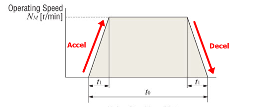
A typical motion profile usually involves three stages: acceleration, constant speed, and deceleration. Let’s break it down:
- **Start from zero speed**
- **Accelerate over a period of t1**
- **Maintain constant speed at Nm for a duration of t0-t1-t1**
- **Decelerate over a period of t1**
- **Stop at zero speed**
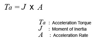
**Acceleration/Deceleration Torque**: Unlike load torque, which remains constant, acceleration torque is the torque required to speed up or slow down an inertial load. It depends on load inertia and the rate of acceleration or deceleration.
The total required torque is the sum of load torque and acceleration torque, plus a safety factor to account for uncertainties:
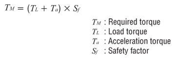
Acceleration torque can be calculated using the following equation:
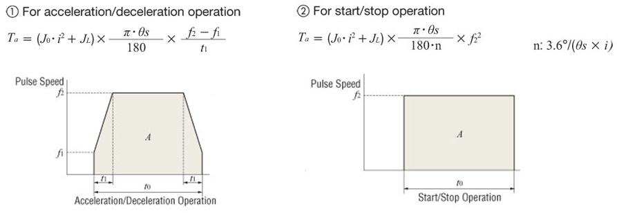
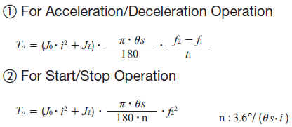
For stepper and servo motors, there are different formulas based on pulse speed (Hz). Here are two equations for motion profiles with or without acceleration/deceleration:
When dealing with linear systems, all linear units like speed need to be converted to RPM or Hz. The goal is to ensure the motor can provide enough torque at the desired speed.
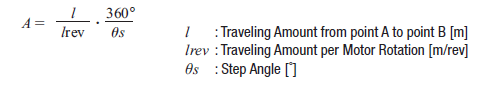
For RPM-based formulas, here’s how you convert linear speed to RPM:
And here’s the formula for acceleration torque:
Alternatively, you can use Hz formulas. Oriental Motor engineers often prefer the pulse formulas:
**Number of Operating Pulses (A)**:
The number of pulses needed to move the load from point A to B.
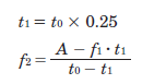
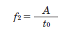
**Operating Pulse Speed (f2)**:
This is derived from the number of operating pulses, positioning time, and acceleration/deceleration time.
For acceleration/deceleration operations, a good rule of thumb is to set the acceleration time at approximately 25% of the total positioning time.
For start/stop operations, the formula changes slightly:
**Tip**: Why use acceleration/deceleration at all?
Even though starting at the target speed might seem simpler, it creates excessive acceleration torque, requiring a larger motor. Larger motors are costly and take up more space, which isn’t ideal for most machine designs.
Let’s walk through a calculation example. These examples have been incredibly helpful for me.
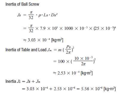
**Step 1: Load Inertia**
First, calculate the load inertia for the screw, table, and load individually, then sum them up. This value helps in choosing a suitable motor.
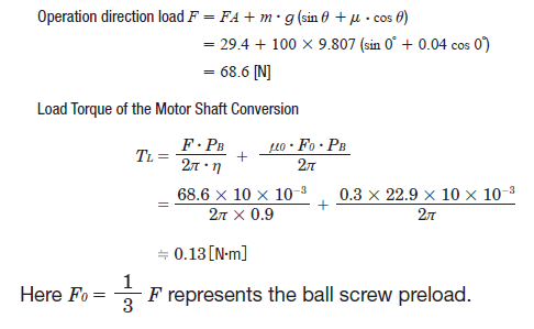
**Step 2: Load Torque**
Use the load torque equation for screws and fill in the necessary variables. Ensure you’re using the correct equation for your specific application.
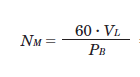
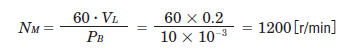
**Step 3: Speed (RPM)**
To calculate the required speed, use the pitch/lead of the screw (PB) to convert linear speed to RPM. In this case, we’re using an RPM formula instead of Hz.
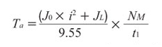
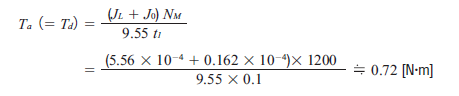
**Step 4: Acceleration Torque**
Here’s a common formula for acceleration torque for all motors:
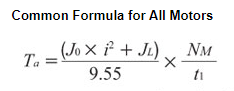
To calculate acceleration torque (Ta), tentatively select a motor based on load inertia. Then plug the rotor inertia value (J0) into the acceleration torque equation. Without rotor inertia from the motor, we cannot calculate load inertia.
**Tip**: How to tentatively select a motor based on load inertia
For AC constant speed motors, AC speed control motors, and brushless speed control motors, check the permissible load inertia values. For stepper and servo motors, consider the allowable inertia ratio each motor can handle.
For stepper motors, aim for an inertia ratio (load inertia or reflected load inertia divided by rotor inertia) under 10:1, and 5:1 for faster motion profiles or smaller frame sizes than NEMA 17. Closed-loop stepper motors can handle up to a 30:1 inertia ratio, while auto-tuned servo motors can go up to 50:1, and manually tuned servo motors up to 100:1.
After selecting a motor, find the rotor inertia in the specs and input the J0 value to complete the acceleration torque calculation.
For Hz-based calculations, here’s another equation for acceleration torque:
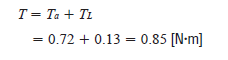
**Step 5: Total Required Torque and Safety Factor**
Add the load torque and acceleration torque to get the total required torque. We’ll need a stepper motor capable of outputting at least 0.85 Nm torque.
Without a safety factor, this works. But with a safety factor of 2, we’ll need a stepper motor capable of producing 1.7 Nm torque at about 1200 RPM, depending on acceleration/deceleration rates.
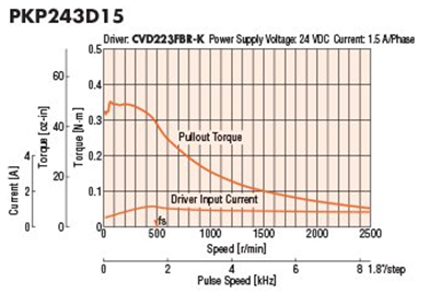
For stepper motors, avoid using the maximum holding torque to size them. Instead, refer to the speed-torque curve to ensure the motor provides sufficient torque at the desired speed.
**Step 6: RMS Torque (Servo Motors)**
For servo motors, another calculation is needed—RMS torque. This is the average torque value over time, considering all varying torque demands. It ensures the motor doesn’t overheat.
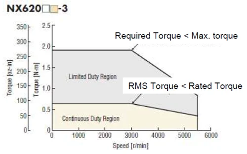
The required torque must be below the motor’s peak torque, and the RMS torque must stay below the rated torque. Peak torque generates high current, which can’t be sustained without risking overheating.
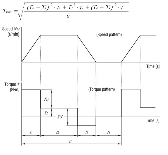
Here’s the RMS torque equation and a motion profile visualization:
For this example, the calculation looks like this:
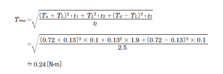
Here, t1 + t2 + t3 = 2.1 [s], with t1 = t3 = 0.1 for acceleration and deceleration times. Thus, t2 = 2.1 - 0.1 - 0.1 = 1.9 [s].
The ratio (effective load safety factor) of Trms and the rated torque of the servo motor (TM) is:
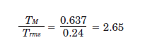
Typically, a motor can operate safely at an effective load safety factor of 1.5 to 2 or more.
**Tip**: More about RMS torque
For more details, check out this article from Linear Motion Tips (Design World).

**Results**
For this application, we need a motor with high positioning accuracy, which means either stepper or servo motors.
**Stepper Motor Requirements**:
- Load Inertia = 5.56 × 10⁻⁴ [kg·m²]
- Total Torque = 0.85 [N·m]
- Maximum Speed = 1200 [r/min]
**Servo Motor Requirements**:
- Load Inertia = 5.56 × 10⁻⁴ [kg·m²]
- Total Torque = 0.85 [N·m]
- RMS Torque = 0.24 [N·m]
- Maximum Speed = 1200 [r/min]
These values don’t include a safety factor.
With torque, load inertia, and speed, we have enough data for motor selection. However, there’s another crucial criterion to ensure long-term reliability—hint: it’s related to bearings. Stay tuned for the next post, where I’ll discuss radial and axial loads.
Here’s a downloadable motor sizing guide (PDF) you can keep handy:

In the next post, I’ll explain radial and axial loads.

Finally, here’s the link to the previous post:

**Tip**: Is there an easier way to size motors?
Yes! Use a motor sizing tool. Unit conversions are automatic, saving you time for other important tasks.

Stay tuned for more insights!