Application
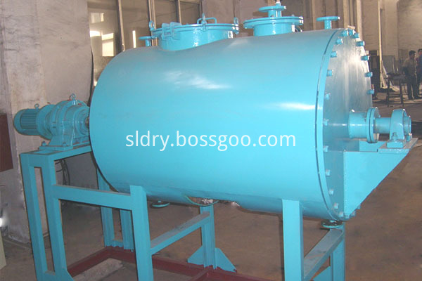
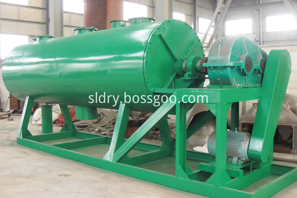
ZKG vacuum harrow dryer equipment is designed for drying slurry, pasty, powdery materials, thermosensitive materials requiring low-temperature drying, easily oxidized materials, as well as explosive materials, toxic materials and the materials whose organic solvents should be recovered. This Vacuum Drying equipment is applied to the pharmaceutical, nourishment, food, chemical and other industries.
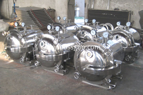
YZG round vacuum dryers and FZG square vacuum dryers are widely used in the pharmaceutical, nourishment, food, chemical, dyes, electronics and other industries. Our vacuum drying machines accord with the requirements of GMP standards.
CHANGZHOU
SULI DRYING EQUIPMENT CO.,LTD.specializing in the production of Mixing
Dryer, Spray Dryer, Granulation DryerCrushing Dryer, 3D Motion Mixer
and V-shaped Mixer.
Vacuum Dryer Vacuum Dryer,Food Vacuum Dryer,Vacuum Hollow Dryer,Medical Vacuum Dryer Changzhou Su Li drying equipment Co., Ltd. , https://www.sldrying.com
The transmission is an important part of the car, and its operating noise is an important source of overall vehicle noise. At the transmission production site, there is an urgent need for a noise detection method that can detect quickly and easily, and can accurately reflect the noise conditions of the transmissions. Off-line detection of the transmission is usually measured directly with a sound level meter under low background noise conditions, which is clearly not available at high background noise production sites. Since the transmission is a closed box structure, the noise of the radiation can be estimated by measuring the vibration of the surface of the transmission case structure, that is, the vibration speed method measures noise.
The application of the vibration velocity method has been studied at home and abroad.
A calculation formula for solving the radiated sound power level of the vibrating plate is deduced. The calculation error is large, and the formula is very inconvenient to use. Although the accuracy basically meets the requirements, it is not suitable for online detection. The vibration speed method in the national standard is used for refrigerator compression. On-line noise detection of the machine has achieved good results, but it cannot be directly used for noise on-line detection of the transmission. In order to further improve the test accuracy and simplify the measurement method, based on the theory of acoustic-vibration coupling, from the energy point of view, through a large number of experiments, the vibration velocity of the main vibration surface of the transmission and the sound pressure value of the radiation noise at the measurement point are found. The proportional relationship and the contribution of the noise radiated by each major vibration surface to the total noise of the measurement point. In this way, the sound pressure of the corresponding surface radiation noise can be obtained from the vibration velocity of the main vibration surface of the transmission at the noise measurement point, and then the sound pressure value of the total noise of the noise measurement point can be obtained, thereby exploring a noise suitable for the vehicle transmission. A new method of online detection.
Constructs 1 efficiency to radiate sound energy. Therefore, for any structure 5, a certain Hz and 2 1 principle deflection (bending) wave is the only structural waveform that plays a direct role in the acoustic radiation of the plate structure. The acoustic wave emitted by the bending wave in the mechanically driven infinite plate is a plane wave, and as shown, the plane wave propagates in a direction perpendicular to the wavefront. In the figure, Ab is the bending wave wavelength of the plate, A is the wavelength of the radiated sound wave, kB is the bending wave number of the plate, kB=2/Aa=o/cb, k is the wave number of the radiated sound wave, k=2R/A=0/c. The acoustic radiation incident on the fluid medium (usually air) at a 0 angle must satisfy A>A or f>/c (/ is the bending wave frequency of the plate, fc is the critical frequency of the plate).
That is to say, the bending wave in the structure propagates faster in the fluid, and the free wave in the mechanically pushed infinite plate can effectively radiate the acoustic energy only when the frequency of the bending wave is greater than the critical frequency of the structure. It is derived from basic acoustics and related formulas that the mechanically driven infinite plate produces a sound pressure level at any arbitrary point (x, y) in the fluid. P—the density of the fluid medium c—the speed of sound UyPmax in the fluid medium—the plate The maximum power of the vibration velocity on the surface is divided by the sound power radiated by a large piston having the same surface area and the same root mean square vibration velocity as the structure. Therefore, the radiation ratio describes the efficiency concept. When compared with the piston of the same area, the mean square vibration velocity v2 of the junction time and space, and the radiation sound power of the W infinite plate are a function of the structural bending wave frequency. The radiant ratio of the finite plate structure is a function of the product ka of the wave number and the structural feature size and the ratio of the bending wave frequency to the critical frequency (///c). 151. Under the semi-free field condition, the total radiated sound power W and distribution of the machine. The relationship between the sound intensity Ir on the hemispherical surface (measuring surface) 2 is that in the far field, there is a very simple relationship between the mean square sound pressure and the sound intensity, that is, by the formula (2) (4) Introduced, a fixed point between the sound pressure value at a certain point in the far field and the vibration speed of the sound source surface satisfying a certain distance from the sound source can be regarded as a certain value, that is, in the above In the case, the mean square value of the sound pressure at a certain point is proportional to the mean square value of the surface average vibration velocity of the sound source.
The transmission is a closed box structure, and 90% of the noise in the noise is radiated by the wall of the box through the solid conduction path to the outside of the box. The shape of the casing of the LC5T97 type automobile transmission is relatively simple. The other surfaces except the bell mouth can be approximated as a plane. Therefore, the radiation noise of each surface of the box has a certain proportional relationship with the vibration of the corresponding box surface, and the transmission box is fixed. The fixed point noise of the distance is equal to the superposition of the noise radiated from each side of the box at this point. Therefore, if we can find the corresponding relationship between the noise radiated from each side of the transmission and the corresponding surface vibration, and the contribution of the noise radiated by each surface to the total noise of a fixed point outside the transmission, it can be accurately compared with the surface vibration of the transmission. The noise at the measurement point is required outside the body to realize on-line detection of transmission noise.
2 Tests and Results 2.1 Spectrum Characteristics Analysis of Transmission Noise The transmission noise measurement point selection and measurement method is performed as follows. A noise spectrum diagram of the transmission V-stop is given. It can be seen from the spectrum that the V-block noise is mainly distributed in the 1004 circle, and the dominant frequency of the noise block (ie, the contribution to the noise is relatively large. 2.2 The outer surface of the simplified transmission structure is composed of the bell mouth, the left side, and the right side. The surface, upper surface, lower surface and rear end surface are composed. The test shows that the noise radiation of the transmission mainly comes from the bell mouth, the left and right sides and the upper surface, so these four surfaces are used as the vibration measuring surface. Run the modal diagram, synthesize the coherence function curve of vibration and noise at each point of each block, and find a point where the vibration is relatively large at each dominant frequency, and the vibration and noise coherence are good as the vibration measurement points. The vibration velocity spectrum of the measuring point 2 on the left side of the transmission V-stop, the noise spectrum of the noise measuring point and the coherence function curve of the two are given. It is the operating mode diagram of the transmission. It can be seen from the figure The vibration of the No. 2 measuring point on the left side is stronger under the operating modes of the dominant frequencies. At the same time, it can be seen that the vibration of the point and the noise of the noise measuring point are in each dominant frequency. The coherence is better, so the measuring point No. 2 is selected as the speed measuring point on the left side. The measuring points on the other side are also determined in the same way. 2 Measuring the vibration signal of a certain surface and the radiation of the surface When the noise signal is used, the measured surface is exposed to the outside, and the other measuring surfaces are tightly wrapped with the sound absorbing material and the sound insulating material, so that the noise radiated by the surfaces is completely absorbed and isolated. The acceleration sensor is installed on the corresponding measuring point. The measured acceleration signal is amplified by the integrated charge amplifier to obtain a speed signal; the sound level meter is placed on the noise measuring point to directly measure the sound pressure signal. At the same time, the above two signals are measured and transmitted to the data acquisition controlled by the upper computer. The data collector transmits the acquired digital signal to the upper computer, stores and waits for processing. Using the above method, the vibration and noise time domain signals corresponding to the four surfaces in each gear are respectively measured.
2.3.2 Data processing Using the frequency domain signal of vibration and noise corresponding to a certain measuring surface measured by the above test, the proportional coefficient of vibration and noise of the measuring surface is obtained according to the octave. The processing flow is as shown in the figure. .
For each ratio, the root is summed, and t is calculated as 4 to measure the spoke. The total times aaaaaaa positive frequency sound system meter 4 sounds are fired on the basis of 1 string chord noise control 2. Noise surface off the acoustic surface 5 trial 4 test: zoom to obtain the corresponding energy value of each face can be used for each frequency multiplier - total The energy of the noise - the energy value of the frequency point and the square of the amplitude of the frequency point, the proportionality coefficient can be determined by the system's positive response to the known energy. The energy of a certain octave is equal to the sum of the energy of all frequency points within the frequency.
According to the previous theory, the vibration of the corresponding surface radiated by each face of the transmission can be approximated as the proportional accuracy of the two-way signal according to the octave. ! Tests facing the total noise contribution index In addition to the packets on each side of the transmission, the total noise signal of the measurement points is measured according to the above method. The total noise of the measuring point and the noise of each shot can also be approximated as the noise signal of each surface at the measuring point measured by the integrated front transmission package, and the contribution of the noise and noise radiated by each surface can be derived. index. The contribution index curve for the total noise calculated for each frequency of the V-stop is given.
In particular, the four accelerometers simultaneously measure the vibration acceleration signal of a certain gear amplitude surface of the gearbox, and integrate the integral speed signal to obtain the required speed signal. According to the relationship between the noise of the radiation and the vibration of the corresponding surface determined above, the octave of the noise radiated by the surface at the noise measurement point is obtained, and then the total noise contribution index of each gear is The octave energy value of the total noise radiated from the transmission, the sum of the process energy is the total energy of the total noise, substituted into the P-sound pressure reference value, 2X10⁻⁵PaK-test environment correction value and system correction, then Find the sound pressure level of the gear noise measurement point.
This method was applied to the noise measurement of the LC5T97 automotive transmission. The test results are shown in Table 1. It can be seen from the table that the difference between the result measured by the method and the measurement result of the sound level meter in the anechoic chamber is not more than ±1 dB except for the No. 2 transmission I block of 1.3 dB. Meet engineering accuracy requirements.
Table 1 Transmission noise measurement results Transmission gear sound level meter Measurement vibration speed method Measurement station number result Empty emptying Invert: No. 1 transmission is one of the transmissions for measuring the relationship between vibration and noise and each surface contribution index; Transmission No. 2 is randomly selected.
3 Conclusion From the above theoretical analysis and test results, it can be seen that for automotive transmissions, the proportional relationship between vibration and noise is present, and it is completely feasible to measure the noise pressure level by vibration velocity. The test method is used for the on-line detection of noise in the LC5T97 automotive transmission. The accuracy meets the engineering accuracy requirements, and the measurement method is simple. The noise test of each gear only takes 78s, which successfully solves the problem of fast and accurate noise transmission to the transmission on the production site. Online detection of problems.
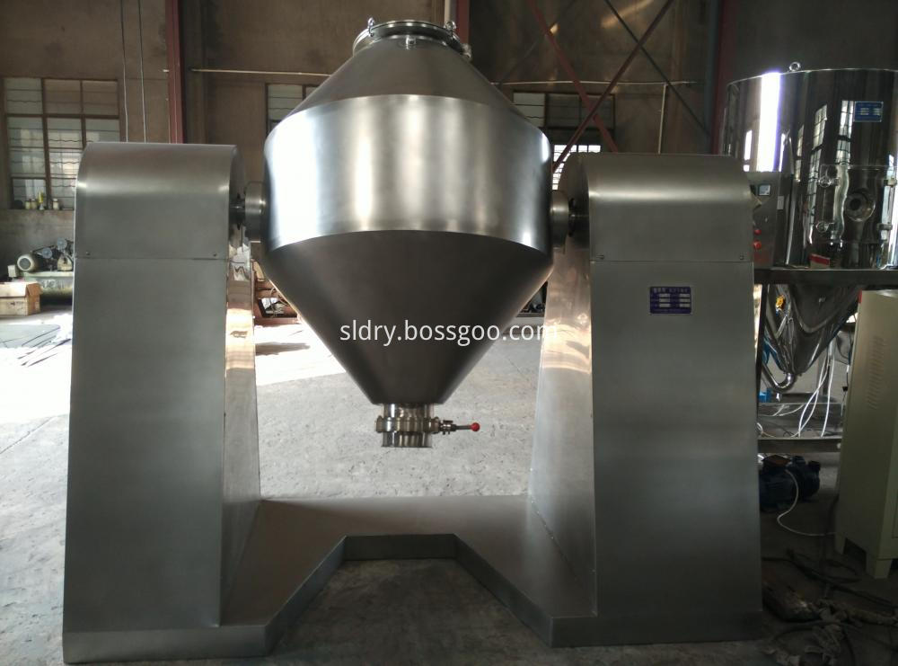
SZG double cone rotary Vacuum Dryer is applicable for drying and mixing powdery and granular materials in the pharmaceutical, food, chemical, dye and other industries.


